General
The modulator plug-in modulates selected signals using a freely selectable signal waveform. The actual signal value, the value to which the slider is set inside the panel, is taken as offset. The following waveforms are available:
•Counter (meter), incremented on each message dispatch
•Ramp
It is possible to overlap several individual noise signals. Optionally, panels can be set to display modulated signals.
Basic functionality and main window

Main window of the modulator plug-in
The dialog contains a table in which lists all the signals and variables to which a signal shape is modulated.
The following operations are available via the toolbar and the context menu:
Operation |
Description |
New |
Opens a browser window to add a signal or a variable |
Edit |
Opens a dialog for editing the modulation |
Delete |
Deletes the selected modulations |
Copy |
Copies the modulation to the clipboard |
Paste |
Pastes a copied modulation |
Import |
Imports a previously exported modulation |
Export |
Exports all modulations to a file |
Active |
Change the Active status of the selected modulations |
Hints:
•New signals and variables can be added easily via drag & drop.
•Editing is also possible by double-clicking or pressing the Enter key.
•The column "A" shows which modulations are active. The status can be changed directly with the mouse or the space bar.
•The column "S" indicates by a red exclamation mark that the signal values are also changed in the panels.
Settings dialog
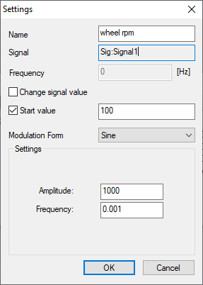
Settings dialog of the modulator plug-in
The settings dialog is used to configure all relevant modulation parameters. Before applying new settings (OK), the validity of the entered data is checked. The individual input fields are explained via Tooltips. Depending on the selected interference signal, different options are displayed.
The following elements are displayed in the top part of the settings dialog:
Setting |
Function/Description |
Name |
Freely definable name for the modulation. |
Signal |
Name of the signal to which waveform modulation is applied. |
Sending frequency |
Inverted value of the cycle time with which the message containing the signal is sent. If this value is ”0”, please check the transmission control of the message. |
Interference signal |
Type of modulating signal. The following are available for selection: sine, rectangle, noise, custom, counter, triangle, ramp. |
Change signal values |
If this box is checked, the signal value changes are also displayed in user panels. When this option is activated, the signal value currently displayed in the panel is transmitted as offset. |
Set signal value |
If this box is checked, the signal value is set to the desired value each time simulation is started. Please note that setting the start value can trigger spontaneous sending of a message. As a result, messages that are already set to spontaneous sending in the transmission control are sent twice in quick succession when simulation is started. |
Settings |
This field contains different settings depending on the selected modulation type. The settings are described below. |
Modulation forms
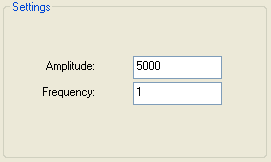
Settings for sine wave
Sine wave
The settings dialog of sine modulation provides only two parameters:
•Amplitude: maximum value of modulated sine wave.
•Frequency: number of sine oscillations per second.
The effects of both settings are shown in Figure 4. In this example, a signal named “Rad1” with a starting value of 8000 is modulated by a sine wave with a frequency of 1 Hz and an amplitude of 5000.
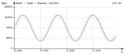
Example of a sine signal
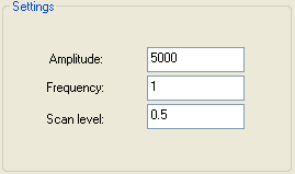
Settings for rectangle
Rectangle
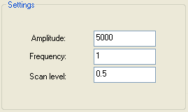
The settings dialog of rectangle modulation provides three parameters:
•Amplitude: maximum value of rectangle signal.
•Frequency: number of rectangle signals per second.
•Duty factor: ratio of positive and negative parts of the rectangle signal (value range: 0 to 1).
In this example, a signal “Rad2” with a starting value of 8000 is modulated by a rectangle with a frequency of 1 Hz, an amplitude of 5000 and a duty factor of 0.5.
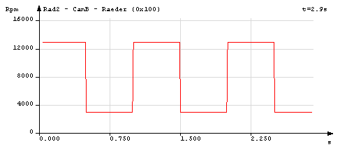
Example of a rectangle signal
Settings for triangle
Triangle
The settings dialog of triangle modulation provides three parameters:
•Amplitude: maximum value of triangle signal.
•Frequency: number of triangle signals per second.
•Duty factor: ratio of positive and negative parts of the rectangle signal (value range: 0 to 1).
The duty factor is characteristic of the interference signal, determining at which point during the oscillation period the triangle’s gradient changes its sign. The duty factor must be between 0 and 1. Any triangle signal (up to sawtooth form) can be generated by modifying the scan level. The significance of the duty factor is illustrated in figures 8 to 11. The amplitude in all figures is 5000, the frequency is 1 Hz.
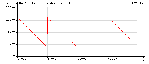
Example of a triangle modulation with pulse duty factor 0
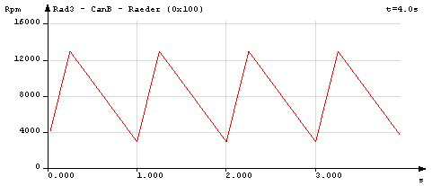
Example of a triangle modulation with pulse duty factor 0,25
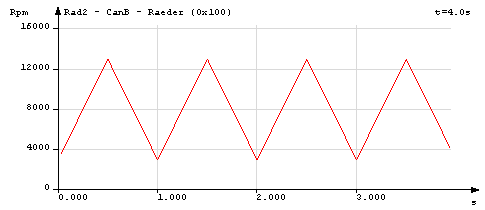
Example of a triangle modulation with pulse duty factor 0,5
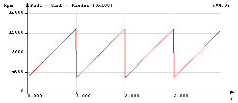
Example of a triangle modulation with pulse duty factor 1
Settings for user specific
Custom
The settings dialog of custom modulation provides the following options:
•"..." Button: selection of a source file with numerical values for modulation.
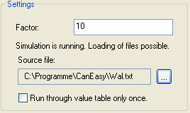
•Factor: multiplier for the values read from the file.
•Source file: shows the path of the current source file
•Run through value table only once: If this box is checked, the number table in the source file is only run once.
If simulation is idle, a text file can be selected by clicking the “…” button (browse button). The file must contain a numerical value in each line.
The numerical values must adhere to the following form:
[Space character/Tab] [Sign] [Value] [.Decimal places] [ {e | E}[sign]Value]
The decimal places can be followed by an exponent that consists of a preliminary character (e or E) and any signed integer.
For example, a value within the table can appear as follows:
+144.675E-14
The value table is run during simulation. Each time simulation is started, the modulation restarts with the first value of the value table. When a message containing the modulated signal is sent, the following entry in the value table is multiplied with the set factor and overlaid on the actual signal value. If the option “Run through value table only once” is selected, no interference signals are overlaid after all values have been used. If this option is inactive, the value table is run in an infinite loop.
A new value file can be loaded only if the simulation is inactive, because loading very large files would affect real time execution of the simulation. If a file cannot be read on loading a workspace, the text in the settings column is shown in red. A tool tip describing the error is shown when hovering over the text. An additional feature is the recognition of file changes since the last import, carried out before the start of a new simulation. If changes are detected, the text in the settings column is shown in orange, and a tool tip providing more information is shown when hovering over the text.
An example of a custom interference signal is shown in the following figure. The value table has 34 values; the factor has been set to “10”. The generated function has been named “whale”.
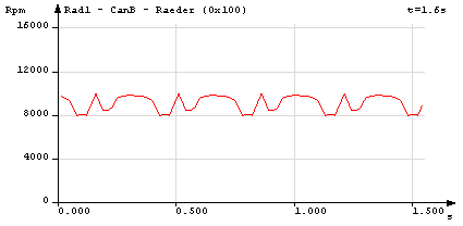
Example of user specific modulation "whale"
Settings for noise
Noise
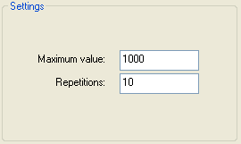
The settings dialog of noise modulation provides only two parameters:
•Maximum value: specifies the highest possible value the noise can reach.
•Repetitions: specifies how often the overlaid noise value changes. In case of zero repetitions, a new noise value is calculated for each sent message. If set to ten repetitions, the noise value only changes on every tenth sent message. The number of repetitions controls the level of noise.
The following figure shows a signal with a starting value of 8000, overlaid with noise using a maximum value of 5000 and 5 repetitions.
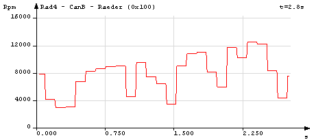
Example of a noise modulation with 5 replays
Settings for counter
Counter
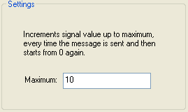
The settings dialog of counter modulation provides only one parameter:
•Maximum value added to the original signal.
For every sent message, a value is incremented (starting from zero) and added to the related signal. When the maximum value has been reached, the counter restarts from zero.
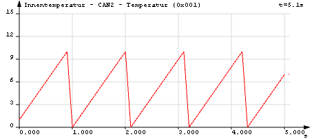
Example of a counter which is counting up to 10
Settings for ramp
Ramp
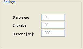
The setting dialog of ramp modulation provides three parameters:
•Start value: starting value from which the signal is incremented.
•End value: value the signal is incremented to.
•Duration [ms]: Time (in milliseconds) the signal takes to reach the end value (from the starting value).
The following figure shows a signal overlaid with a ramp with a starting value of 10, an end value of 100, and a period of 1000 ms.
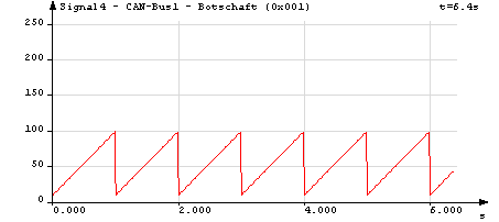
Example of a ramp signal